

The Case of GRS1915 | Definitions of lag | LAG : a simple derivation | Application
Microquasars - LAG Model / Lag : a simple derivation
One can reproduce the observed behavior of the lag and harmonics using simple assumptions about the initial profile. The idea is to compare the Fourier representation of an initial profile (here a constant plus a cosine) taken to be the hard X-ray, to a modified profile taken to be the soft X-ray. We will then compute the lag between them and show a simple way to match the observed lag behavior.
If we compute the Fourier Transform of a sinusoid function we obtain the frequency, amplitude and phase. In order to make it similar to data we take the sinusoidal profile surimposed on a constant background and add a small amount of random noise to it. By using the FT we still find the frequency, amplitude and phase. Now take into account the case where some part of the modulated emission does not arrive to the observer but a part of it is absorbed/obscured by a media located in the system. This would make a profile similar to the one of Fig. 1

Figure : [Morgan et al. (1997)] studied GRS 70#70 timing variability using average QPO-folded profile for the 71#71 Hz QPO. The profile show an absorbed-like feature for the soft energy band (72#72 keV) emphasized on the figure by the grey "missing part''. [Morgan et al. (1997)] also showed the QPO profile at higher (hard) energies. For higher energies, the profiles appear more sinusoidal, i.e. the "missing/absorb part'' becomes smaller.
Table 1 shows the Fourier Transform
using an input profile of unity plus a sinusoid with rms amplitude rms = 0.14
minus a Gaussian profile of amplitude ![]() centered to
reproduce a profile like the one from the Fig. 15 of Morgan et al. (1997)].
The first line is the representation of the initial
state, the test # 1 shows the first two frequencies of the Fourier representation
of the absorbed signal.
centered to
reproduce a profile like the one from the Fig. 15 of Morgan et al. (1997)].
The first line is the representation of the initial
state, the test # 1 shows the first two frequencies of the Fourier representation
of the absorbed signal.

Table : Representation obtained from the FT of a signal ![]() plus an absorption of amplitude
plus an absorption of amplitude ![]() .
.
We see that by doing the FT on this signal we obtain different parameters for the sinusoid. Depending on the amount of "absorption'' we can obtain a smaller value for the amplitudes, but the striking feature is the effect on the phase : a change is observed. Moreover, the sign of the phase difference is not the same for the fundamental and its first harmonics.
If we take the formula for phase lag and say that only the low energy/soft X-rays are absorbed and not the hard ones we can compute the phase lag which appears as a consequence of the absorption of only part of the signal. Doing so reproduces the observed phase characteristics : a different sign for the fundamental and first harmonics. In addition, if the absorption is turned on, it creates a change in the sign of the lag.
This comes from the fact that the FT adjusts the data with a shifted sinusoid, creating
a phase difference. We propose that this is the origin of the changing sign of the lag presented in the
previous section. This will also decrease the coherence between the two bands
as a new signal is added to only one band. This happens without changing the primary physical
phenomena that produces the emission in the two bands.
The above results can be easily illustrated even using two sinusoidal signals with a ![]() phase between them :
phase between them :
 (2)
(2)
The presence of a second, small, sinusoidal signal with a phase lag of ![]() and
an amplitude
and
an amplitude ![]() is
enough to create an "apparent'' phase lag of
is
enough to create an "apparent'' phase lag of ![]() , which is
about
, which is
about ![]() , the amplitude of the perturbation.
, the amplitude of the perturbation.
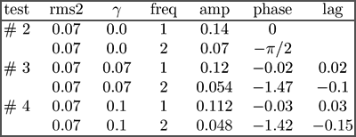
If we now add the presence of a small harmonic to the QPO (of amplitude label rms2 in table 2) and compare the result from the FT to that with the the same signal absorbed, the effect on the phase is even more striking. Table 2 shows the results of such a simulation. Indeed, the induced phase lag between the real data and the absorbed one does not have the same sign at the fundamental vs. the first harmonics. This could be at the origin of the observed phenomena. In this work we show that an absorption of the low energy part of the signal will give the sign difference in the lag and also explain the observed change of sign for the fundamental.

Table : Representation obtain from the FT of a signal
< ![]() plus an absorption of amplitude
plus an absorption of amplitude ![]() .
.