The Unified Board (Version 5)
J.M. Brunet, S. Colonges, B. Courty, L. Guglielmi,
J.J. Jaeger, G. Tristram and J. Waisbard
Collège de France - Paris
I. Pepe - UFBA - Brazil
December 2001, 21 th
1 Introduction
In the Engineering Array (EA), the Local Station prototype modularity was
the main concern behind the conception. Five different boards were plugged
on two towers on top of a mother board.
In production phase, this mother board is replaced by a denser single
board containing :
-
a Power Supply system
-
the CPU core (CPU)
-
the Time Tagging (TG)
-
the Slow Control (SC)
-
an interface for the GPS, FE and LED Flasher modules
-
Front Panel connectors
-
The conception should allow easy production testing and mounting, including
possibility for future extensions. It must give high reliability for 20
years of life with minimum maintenance in difficult environment ( -20 to
+70 degrees Celsius with high day variation, humidity due to water staying
on salt ground and water tank proximity)
-
The mean consumption must be closed to 10 W
THE CPU CORE :
-
Power PC 403GCX 40/80MHz - 32bit data and address - cache running Microware
OS9000 (Unix-like Real Time)
-
32 Mo EDO DRAM
-
4 Mo in system programmable Flash memory
-
An in system programmable PLD for flexibility
-
DMA channels are used for fast FE data transfer
-
A 4 serial ports peripheral is used for communication with other devices
(GPS, Telecom, TPCB, external test device).
-
A connector is provided to connect an Ethernet interface for software development
and board tests.
2 Mechanical Constraints
To minimize cabling and feed-through hardware, the SDE group and the tank
designers have decided no longer to use the EA electronic enclosure concept.
The Local Station (in a metal box) will be located on top of hatch-cover
1, inside of a plastic weather proof box with (400 x 400 mm) maximal dimensions.
As in the preview design, the metal box plays a EM shielding role, so far
its dimensions are not yet determined.
The Unified Board dimensions are setting to 240*340 mm (4 to 6 layers).
For humidity protection, electronic box will be tropicalised.
The CDF team, had suggested during September 2001 workshop, to install
a roof under the plastic box on the hatch cover, to permit air flow between
the two pieces, then, to protect the electronic inside the box against
the sun effects. This proposal is not yet accepted by P.O.MASUR in charge
of plastic box design.
3 Electronic Hardware
In a precedent meeting, the SDE group has decided that the unified board
will be, for good, spread in two parts. Initially, for the R&D needs,
the connection between the CPU and the FE will be made using a DIN 41612
(for signals) and HE10 (for power supply) connector, being finally replaced
by soldering pins in the production phase. In that sense, we have, what
we can call, a Local Station final design (see next section). For pre-production,
females connector are mounted on the unified board.
4 The Proposal
The concept presented in figure 1 shows the whole electronic hardware as
part of one single PCB, except for the FE module. There is no motherboard,
the CPU, the Time Tagging and the Slow Control are redesigned, forming
a whole new card, where the GPS card will be connected and mechanically
attached. In the production phase, the GPS card connection will be also
made by soldering pins. On top of the new PCB, one can see four different
sets of connectors. The first set concerns the FE, the old version PC104
(carrying the CPU Courty bus), makes place to a new DIN 41612 (96 pins),
carrying the digital signal and digital power supplies to the FE. A smaller
connector (HE10 type) will be used to transport the analog power supplies
and the analog ground to the analog part of the FE.
Finally a fourth single (34 pins) HE10 connector will provide the CPU
bus signals for the Ethernet card (ETH). A bus buffering interface will
assure the reliability, the EM safety handling and the plug-in compatibility,
between the ETH card and the CPU. This may be done only for pre-production.
Then Ethernet will be deported with this new design, as consequence stability
with Ethernet will be lower. We must keep in mind, that Ethernet was provided
principaly for laboratory software development, and test. For a simplest
way of communication and programmation for new UB, and for operations in
the field, we will use in the new UB a serial port with a PPP protocol
communication. Note that Ethernet connector will be not provided on the
front panel connector, but only on the UB.
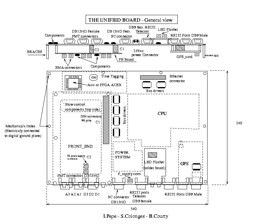
Figure 1 :Unified board electronic hardware
5 Power supply
For the Engineering Array, we are using a full homemade power supply, mounted
on the motherboard's back-plane. Initially for the Unified Board we was
planing to have a customized single package industrial-crafted solution.
Actually, we are testing 3 different solutions :
*After several cost estimations, turns out that we will need to make
a compromise between the homemade and the industrial solutions. In that
sense, for the whole digital circuitry we are planing to use the same homemade
concept, nevertheless we must minimize component dimensions (capacitors,
shelf etc). For the analog section, as its power supply quality requirements
are lot more restrictive, we are planing to use a of the shelf industrial-crafted
switched power supply.
*Using shelf industrial-crafted switched power supply, for all the supply.
This solution is better for reliability, but cost is a little higher.
*Using shelf industrial-crafted switched power supply for 12, +3V3 digital
and +5Volts sections and switched regulator low power (Linear) for +/-3V3
analog section.
Power system protection :
In the Unified Board, we plan to have a electronic basic circuit, to
shutdown the power supply on the UB during a specified time (closed to
3 hours) after had sent an alert to the CPU (during one minute), if an
under or voltage occur, or if temperature on the UB is too high.
For a complete information on power supply, see reference [1].
6 FRONT END INTERFACE PIN-OUT AND DEFINITION
Local bus signals connector C1 - 2.54mm - 3x32 - type DIN 41612
- male on UB, female on FE
| Signal name |
View from UB |
Function |
Pin number |
|
| LA 29 |
O |
Local Address |
C3 |
| LA 28 |
O |
Local Address |
A4 |
| LA 27 |
O |
Local Address |
C4 |
| LA 26 |
O |
Local Address |
A5 |
| LA 25 |
O |
Local Address |
C5 |
| LA 24 |
O |
Local Address |
A6 |
| LA 23 |
O |
Local Address |
C6 |
| LA 22 |
O |
Local Address |
A7 |
| LA 21 |
O |
Local Address |
C7 |
| LD 31 |
I/O |
Local Data |
A12 |
| LD 30 |
I/O |
Local Data |
C12 |
| LD 29 |
I/O |
Local Data |
A13 |
| LD 28 |
I/O |
Local Data |
C13 |
| LD 27 |
I/O |
Local Data |
A14 |
| LD 26 |
I/O |
Local Data |
C14 |
| LD 25 |
I/O |
Local Data |
A15 |
| LD 24 |
I/O |
Local Data |
C15 |
| LD 23 |
I/O |
Local Data |
A16 |
| LD 22 |
I/O |
Local Data |
C16 |
| LD 21 |
I/O |
Local Data |
A17 |
| LD 20 |
I/O |
Local Data |
C17 |
| LD 19 |
I/O |
Local Data |
A18 |
| LD 18 |
I/O |
Local Data |
C18 |
| LD 17 |
I/O |
Local Data |
A19 |
| LD 16 |
I/O |
Local Data |
C19 |
| LD 15 |
I/O |
Local Data |
A20 |
| LD 14 |
I/O |
Local Data |
C20 |
| LD 13 |
I/O |
Local Data |
A21 |
| LD 12 |
I/O |
Local Data |
C21 |
| LD 11 |
I/O |
Local Data |
A22 |
| LD 10 |
I/O |
Local Data |
C22 |
| LD 9 |
I/O |
Local Data |
A23 |
| LD 8 |
I/O |
Local Data |
C23 |
| LD 7 |
I/O |
Local Data |
A24 |
| LD 6 |
I/O |
Local Data |
C24 |
| LD 5 |
I/O |
Local Data |
A25 |
| LD 4 |
I/O |
Local Data |
C25 |
| Signal name |
I/O |
function |
Pin number |
|
| LD 3 |
I/O |
Local Data |
A26 |
| LD 2 |
I/O |
Local Data |
C26 |
| LD 1 |
I/O |
Local Data |
A27 |
| LD 0 |
I/O |
Local Data |
C27 |
| EXT_TRIG |
O |
External trigger |
A1 |
| -CAS 3 |
O |
Col. Addr Strobe (DRAM) |
A11 |
| DRAMWE |
O |
Write Enable (DRAM) |
A2 |
| -CS 4 |
O |
Chip Select FE trig |
A10 |
| -CS 6 |
O |
Chip Select prog feature |
C10 |
| -DMAA 0 |
O |
DMA ACK FAST |
A9 |
| -DMAA 1 |
O |
DMA ACK SLOW |
C8 |
| -DMAA 2 |
O |
DMA ACK SPARE |
A8 |
| DMADXFER |
O |
DMA - synchro |
C1 |
| EVTSYNCS 0 |
I |
Event Synchr. Slow |
C29 |
| EVTSYNCF 0 |
I |
Event Synchr. Fast |
A29 |
| EVTSYNCF 1 |
I |
Event Synchr. Fast |
A30 |
| EVTSYNCF 2 |
I |
Event Synchr. Fast |
C30 |
| -EVTCLKS |
I |
Slow trigger EvtClk |
C28 |
| -EVTCLKF |
I |
Fast trigger EvtClk |
A28 |
| -OE |
O |
Output Enable |
A3 |
| -R/W |
O |
Read/Write |
C2 |
| TC 0 |
O |
End of transfer |
A31 |
| TC 1 |
O |
End of transfer |
A32 |
| SYSCLK |
O |
CPU CLOCK |
C32 |
| -RESET_FE |
O |
Reset |
C9 |
| BUSERR |
I |
Bus error |
C11 |
| GND |
|
Digital ground |
C31 |
| GND |
|
|
B<1..27> |
| GND |
|
|
B31, B32 |
| VCC |
|
Digital +3.3 V |
B<28..30> |
Analog power supply connector C2 - 2.54mm - 2x5 - e.g. HE10 - male
on UB, female on FE :
| Supply name |
Pin number |
Description |
|
| AP3V3 |
1, 3 |
Analog supply +3.3v |
| AM3V3 |
7, 9 |
Analog supply -3.3v |
| AGND |
2, 4, 5, 6, 8, 10 |
Analog ground |
For the development and tests connectors could be used, with standard DIN41612
spacers should be 17 mm long. For the production the modules will be soldered
then spacers will have to be smaller, e.g. 8 mm long or less.
Table 1. FE connection list.
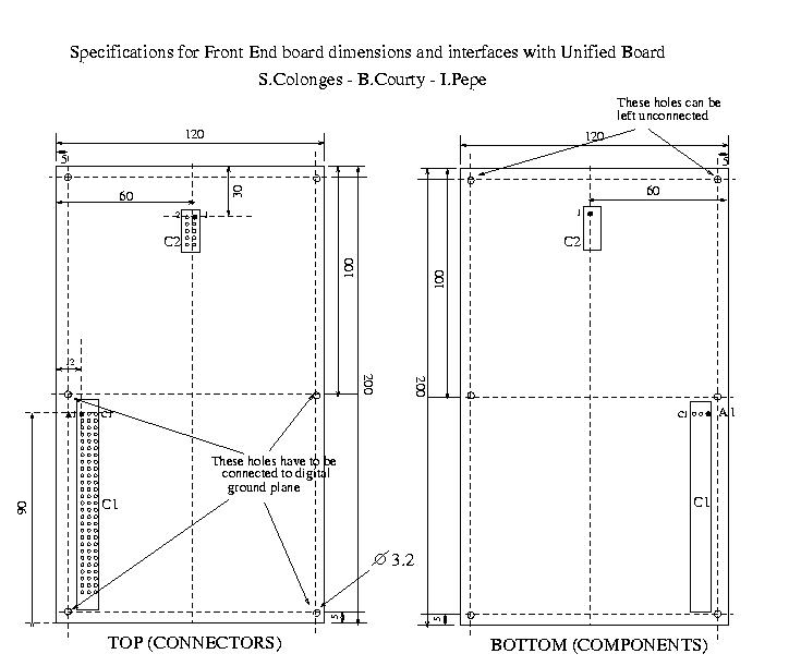
Figure 2 : specifications for Front End board dimensions
7 Connectors
7.1 The front panel connectors are as follows:
1) Radio serial - DB9 female, Leeds pin-out
2) Console Serial - DB9 male
3) TPCB serial - DB9 male
4) ``Spare'' serial - DB9 male
5) PMT Power (x3) - DB15HD female
6) PMT anode and dynode inputs (SMA female, on front end, 6 total)
7) LED driver outputs (SMA female, 2 total)
8) Sensor cable - DB15HD female (with water level, air temperature inside
or outside, external trigger input)
9) Power connector - two pins per B. Courty
10) Grounding plug on box exterior controller software
7.2 UB to PMT Connections
For the EA the SDE group decided to use a DB15 HD female for each PMT.
This connector will transport the following signal:
-
+3.3V analog section voltage ; GND
-
-3.3V analog section voltage ; GND
-
+12V high voltage supply ; GND
-
DAC (high voltage) control signal ; GND
-
High Voltage (voltage) read-back ; GND
-
High Voltage (current) read-back ; GND
-
Temperature Sensor ; GND
The cable chosen is a 7 twisted pairs (this is to confirm with Joel POUTHAS),
24 AWG, no shielding, and we are planing to install a 20 mm long ferrite
ring at one end, to minimize the common mode noise. For PMT output signals
we are keeping the same EA (SMA) connectors. The slow control and the 3
signal cables will be tied together in order to avoid ground loops. All
3 PMT cables will have exactly the same length, those used for the PMT
in hatch 1 will be tied together, as tight as possible, to minimize the
cable slack, avoiding cable and ground loops.
Concerning the weather protection treatment, the PMT will be definitively
attached to its base by soldering and finally the whole set will be potted.
Once the PMT, the base and the cables are tested, the set will be potted
together for good.
8 LED FLASHER :
-
For the pre-production we plan to have a daughter board on the UB for Led
Flasher command unit.
-
For production, we need to discuss about a possible integration of the
Led Flasher command unit in the UB.
-
During the September SDE workshop, we have decided to two led at one location
offset from the center toward a hatch cover, so that the LED can be repaired
after liner installation if necessary.
-
Connection between UB and Led Flasher is a HE14 type connector female
-
2 SMA connectors are used the connection between command unit and the 2
LED's.
9 Time Tagging :
We are studying two solutions in parallel, the ASIC solution, that seem
working well, and a backup solution consisting of the use of PLD ACEX.
For pre-production, we plan to have the two footprint (one for each solution)
on the unified board. The final choice, then, should be made for the production
after a full test of each solution.
10 GPS receiver :
-
For production, GPS module will be soldered on the UB.
-
A buffer is used between GPS and electronic of the UB.
-
HE10 connector on the UB will provide to access to GPS signals.
11 Sensors and monitoring:
For the Unified Board, the list is reduced to essential sensors to achieve
16 channels of ADC, to simplify the unified board slow control section.
The TPCB does all solar power monitoring.
-
PMT temperature (× 3)
-
PMT HV monitor (× 3)
-
PMT current monitor (× 3)
-
Unified board temperature
-
Unified board voltages (× 4)
-
We will probably add measurement for 3 other voltage on the UB and the
current input of UB
-
2 spare (water temperature + water level?)
During the review of the PMT bases, the need for a water temperature to
assist in the corrections for changes in the photo-cathode temperature
was discussed, and it was agreed that one of the two spares would be used
for this. This temperature may also be useful to monitor tank freezing.
The other spare will be reserved for a water level sensor. There was some
discussion of the need for a water level sensor at all, and if there is
a need what the real requirements were for it to be useful. Since this
cannot impede unified board development, it has been decided to place the
last ADC input on the same connector as the other spare (now reserved for
the water temperature sensor). 12V will also be on this connector because
it is required for the water temperature measurement. Any water level sensor
must make use of the resources made available on this connector.
12 Slow Control
-
All sensors and monitoring for Slow Control are described above
-
J.Beatty purpose to reduce the multiplexer capacitance
-
16 ADC inputs (14 + 2 spares)
-
4 DAC outputs
-
4 digital outputs (3 for addressing LEDs + 1 spare)
-
Impedance input for each way is set to 10 Kilo-Ohms
-
We use a buffer for DAC outputs
-
ESD protection are provided on ADC inputs (protection against electrostatics
discharges)
13 Test equipment and procedures:
L.A.L. laboratory (Orsay - France) is designing a test bench for all
parts of the unified board. The Front End board, and the LED flasher will
be tested separately. The status of the TPCB is still pending.
This will be done by connecting a PC with Linux system and ADC/DAC
interfaces and using a specific electronic board to test interface between
UB and FE. We must test all bits and signal (DMA, chip select...) on this
interface with a simple electronic design. The software test will be running
in both controller and PC with exchange information via Ethernet and/or
the terminal serial port.
The test bench, is in a first step designed to test in a same time
only one UB. A multiple test in the same time, will be study after this
first step (maximum 5 UB tested in the same time).
We plan to have a complete test in temperature only for prototypes
and samples of pre-production and production, to study the performance
of the UB ( Tests with the test bench connected to the UB, with temperature
cycling between -20 and +70 Deg / C, during 48 hours at least).
For the rest of the production, we plan to do a burning, with UB powered
on, and a simply test mode (without a complete test bench in the oven).
We plan to have test bench in the factory, in the PCC laboratory, LAL
laboratory and in Malargue in a first time.
Temperature range should be set between -20 Deg/C and 70 Deg/C
For Burn in, we plan to do 3 cycles with temperature cycling between
-20 and +70 Deg/C during 6 hours, fallow with 16 hours at 70 Deg/C (This
is the purpose of the Front End team). Then, the total time for this burn-in
is 22 hours.
The first test bench should be ready for April or May 2001.
The principal components to test are :
-
Micro-controller must bootstrap correctly
-
Power supply : 4 voltages are monitored directly by Slow Control (battery
input , 12V, 5V and 3V3 digital. We will probably add the measurement of
the + and -3V3 analogical section and of the GND). We can use the power
supply connector for Front End to allow ADC measurement for the other supply
(+ and - 3V3 analog)
-
Ethernet or serial port : at bootstrap, the CPU tries to find Ethernet
board (if we use it), or serial port, load the OS9000 software test from
the PC. In the first step, our decision is to work for test with a serial
port (perhaps with PPP protocol).
-
Serial IOs : just by connecting RX-TX and RTS-CTS on each RS232 port
-
Serial port GPS : Rx/Tx, 1PPs; We use an HE10 connector for access to GPS
signals
-
Slow control DAC and ADC : we need to measure the DAC outputs (3 to control
HV PMT bases, 1 internal output trough an HE14 connector for LED baseline).
Our purpose, is to have an electronic board with 3 continuous amplifier
(*2) with 2 outputs. The amplifier output, then is connected to the input
ADC on the Slow Control used for PMT high voltage monitoring. Then, with
the same scale, if we write data on the DAC, the read on the ADC must be
the same (if note, we probably have a problem of bit, or linearity...)
We need to use a free input ADC to test LED baseline DAC output. We need
to have 3 temperature sensors on the electronic test bench board to test
ADC inputs for PMT temperature measurement (we only want to test that teh
measurment chain is good). Connectors used on the test bench must be compatible
with Unified Board connectors. We need to test also the 3 PMT current monitoring
with tested the related ADC inputs. This can be done by applying a continuous
voltage on this 3 input.
-
For the LED Flasher module, we need to measure the DAC output and the 3
logical outputs from Slow Control towards the LED Flasher.
-
For the test bench we need an external power supply controlled by PC with
a sufficient power, to provide between 18 and 30 Volts continuous.
-
To provide the interface Front End test, we plan to use one PLD board (Given
by Zbigniew) with is config file. Then, we should build an interface board
for this PLD board (we don`t need the analog Front End board). We plan
to have, on this interface some ADC to measure the +/- 3V3 voltages for
analog section. We should use this interface board, to put on all the electronic
needed for the test bench.
-
To test the FE interface, we need to use the calibration routine, write
and read data in PLD, we need to test the DMA...
-
To test the Time Tagging, we can generate an external trigger, and 15 micro-seconds
latter go to read the Time Tagging.
-
To provide this tests, GPS (UT+ by MOTOROLA), should be mounted (deported)
on the test bench bench. We don`t need the antenna GPS to provide this
test.
-
Having a connector for the FE board seem preferable than a soldered board,
for tests, cost, and reliability (If not, we need to have a special connector
for test the interface with FE). This is an open question!
-
All the access routines for the hard and communications functionnality
should be present in the flash (or at least in the Ram Disk) before the
test. All OS9 usefull files, will be given by Laurent GUGLIELMI, to enable
the development of the software for the test bench by the LAL team.
-
We must have a look on the electromagnetic compatibility. At least, we
need to use a simple metallic box to provide a good EMC. We should fallow
specifications given by the industrials...
14 EMC considerations
The unified board will be located on top of the large hatch cover (hatch
1) mounted in an inner metal enclosure. The whole set will be placed into
a plastic weather proof box. The two main issues, concerning this enclosure
design, are:
-
Permits the signal and control cabling to reach the inside of the tank,
but keeping light and environmental sealed.
-
Avoid any RF and/or LF noise interference on the UB.
For power supply, just one (common) ground, being the zero volt reference
for all the electronics parts. This common ground will be connected to
the RF aluminum box and, if possible, connected to the battery negative
pole either. For an electrical shock hazard prevention, we would have the
solar panel brackets and the antenna mast at this very zero volt potential
reference. We must keep in mind, that the first objective in EMC, is to
minimize all the ground loop. Then, we must very carefully, with the link
point of all ground. In the actual design, all grounds are linked in 3
points (UB power supply, front panel connector and PMT bases). See reference
[1].
To minimize the virtual capacitance between the box bottom plane and
the UB the UB ground plane must be tied to box at least every 100 mm. The
same scheme must be adopted for the FE - UB fixation with brace brace,
so, the longer side would have 3 contacts points and the shorter side 2
contacts.
Note: We must pay attention to the mechanical assembling quality of
the contact points between ground plans, otherwise the LS could suffer
of a capacitive coupling with the environment!!!!!
To avoid any RF frequency on the UB, with passing cables, all connectors
will have their metallic part grounded and electrically connected to the
front panel.
To protect electronic against electrostatic discharges (ESD), we will
use some protections components against ESD (the SurgX family by COOPER).
We want to protect in&outputs connected to external signals source.
Some safety considerations :
A floating electric powered equipment is a safety issue. The tank accumulates
electrical charges, and the electrostatic potential increases, becoming
an electrical chock hazard for humans and electronic circuits. Moreover,
the tank is not lightning protected. As a full electrical protection of
the tank, i. e., a high quality ground electrode (capable to be the Earth
or Safety ground), a lightning rod and its appropriate cabling, a lightning
protection for the radio unit, a metal grid or a conductive paint all over
the tank, would be an expansive and complex issue for installation and
maintenance, we are not considering this possibility, unless as an ultimate
solution. What we are doing by now, is bet that a floating tank can remains
out in the pampa for good, working fine. In that sense we would to point
out some preventive measures, once working in tanks electronics:
-
Use an anti-electrostatic carpet, connected to the zero volt reference
(solar panel brackets).
-
Use an anti-electrostatic bracelet, connected to the zero volt reference
(solar panel brackets).
-
Be careful during the cabling, avoiding large cable loops in order to prevent
large inductive areas and a pick-up coupling. providing an indirect-impact
lightning protection.
15 Quality
Quality insurance :
-
In our public tender we have asked for the ISO 9000 quality insurance (or
equivalent), technical and man power resources, tests procedures, production
logging system and boards backtracking.
-
The boards reliability is defined by the MIL-HDBK-217F standard (ground
fixed conditions)
-
The MTBF index is determined and must be equal to the Auger life time.
16 References
[1] The Power Supply Procurement for the Unified Board
of the Surface Detector The Pierre Auger Project
[2] http://cdfinfo.in2p3.fr/experiences/Auger/work.html: ``Local Station
Controller User Manual''.
Retour
File translated from TEX by TTH,
version 2.51.
On 21 Dec 2001, 16:49.